First 8 weeks of work:
Most of my work in this time has been recorded and uploaded to an earlier entry in my blog:Rest of Semester Work:
The rest of the semester involved receiving tasks from our client Hank and delegating certain sections to each team member to complete. The first few weeks involved converting some of his hand drawings into computerised section drawings in AutoCAD.
The first initial drawings and his sketches can be found in the Individual Milestone Submission link.
Section Details
The following are updates of the sections that I had received to complete:
Section 2)
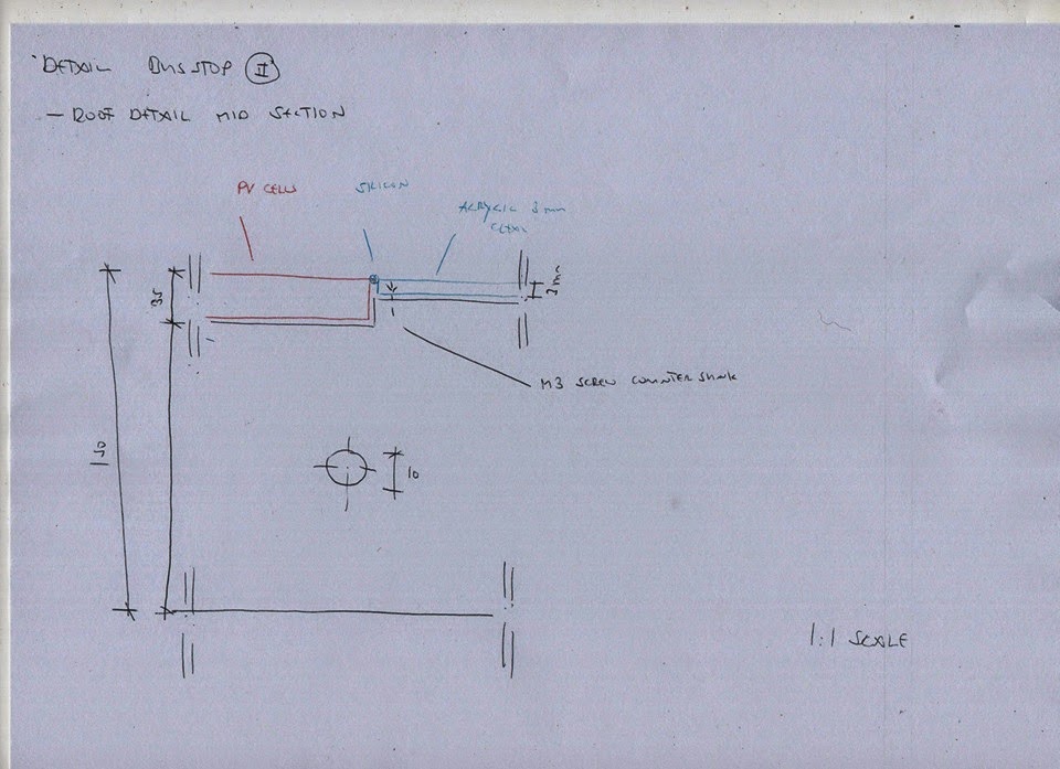
Hank Sketch

Initial CAD Drawing

Added Annotations

Included Roof Pitch after review by Hank

Inserted the 1mm thick Silicon gap between the wood, PV Cell and Acrylic.
Section 6a)

Initial Hank Sketch

Initial CAD Drawing

Initial CAD Drawing
These initial interpretations of Hanks drawings were found to be incorrect. The following CAD Drawings are the fixed versions in compliance with Hanks wishes.

Initial CAD Re Draw

Added Components

Added Roof Pitch

Created gap for cap screw to fit in

Initial Variant - Lengthen the angle bracken for added stability

Added annotations

Variant - included roof pitch

Initial 30 x 60 Minitec Profile in Section

Added roof pitch and 1mm gaps around cap screws

Added the cut out for the cap screw to fit
Timelapse outlining work:
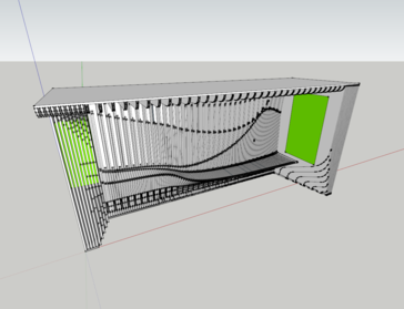
The video is made using Chronolapse captures of my work creating the many variations of my Section 2 and 6a Details.
These variations included:
- 30mm x 30mm Minitec Profile
- 30mm x 60mm Minitec Profile
- Angle Brackets
- Nuts and Cap Screw arrangements
- Various 1mm gaps
- Roof Pitch
The video also includes parts in which I researched the Minitec website and found the plans and details to correctly use in the section details. This meant that the sections were totally correctly and ready for the model making phase.
It also contains parts where I was on Facebook keeping in contact with Jason Lo who I was working with on Section 6. This allowed us to transfer files between us and create our individual parts for the presentations.
It also contains parts where I was on Facebook keeping in contact with Jason Lo who I was working with on Section 6. This allowed us to transfer files between us and create our individual parts for the presentations.
Section 2
Section 11
Laser Cut Files:
Settings:
- 0.025 point line weighting
- RGB Red (R=255, G=0, B=0)

Section 2
Plywood 3mm Thickness
Needs to be cut 3 times in order to create a model of 3 x 15mm sections.

Section 6a
Plywood 3mm Thickness
Needs to be cut 8 times in order to create a model of 3 x 15mm sections.

Section 11
Only created to help Darren as he didn't have illustrator on his computer.
MDF 3mm Thickness
Needed to be cut 5 times in order to create a model of 3 x 15mm sections.
Laser Cuting Of Models:
The beginning of the video contains me going through selecting appropriate settings for the laser cutting machine. I set the power at 100% and the speed at 5% in order to cut through the material properly.
In previous sheets the laser didn't always cut straight through. This was partly due to the fact that the material we were using was plywood and sometimes it can be a warped piece. This causes the point of the laser to not be set correctly as it moves around the sheet, causing it to not cut completely through.
The slowing of the speed worked at cut through all 3mm sheets perfectly.
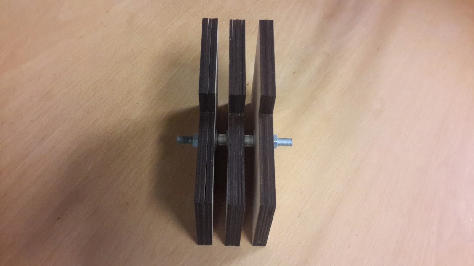
Laser Cut Models:
Section 2
Constructed and Laser Cut by me, using my AutoCAD File.


Section 6
Constructed and laser cut by Jason Lo, making use of my AutoCAD files.


Wiki Spaces Contribution:
As part of my Wiki Spaces contribution I uploaded all my files and images of the work I had contributed to the group.

Files such as those for Section 6 were already uploaded by Jason as he had been working on them to laser cut the model.
Bus Stop Calculations:
After the week 13 group presentations we had a group meeting at ARUP Engineering with our Client Hank and 3 of their engineering employees.
After the meeting they asked us if we could finalise some calculations of the bus stop such as weight and connections.
I took it upon myself to get these calculations started by using George and Michael's 15mm sheet Bus Stop Revit File to create new sections and dimensioning.
I used this to calculate things such as:
- Minitec Framing Lengths
- Minitec Framing Weight
- Number of Sheets
- Number of Connections
- What is in each connection
- etc
The following is what I have managed to achieve before the final submission:


The work contains images gathered from the research i did on the Minitec Website including finding the correct components and their weights.
Files For Download
The following folder link contains the updated Revit file that I used. It also all files that were used to present evidence of work in the blog as well as containing the word document of the calculations above: